


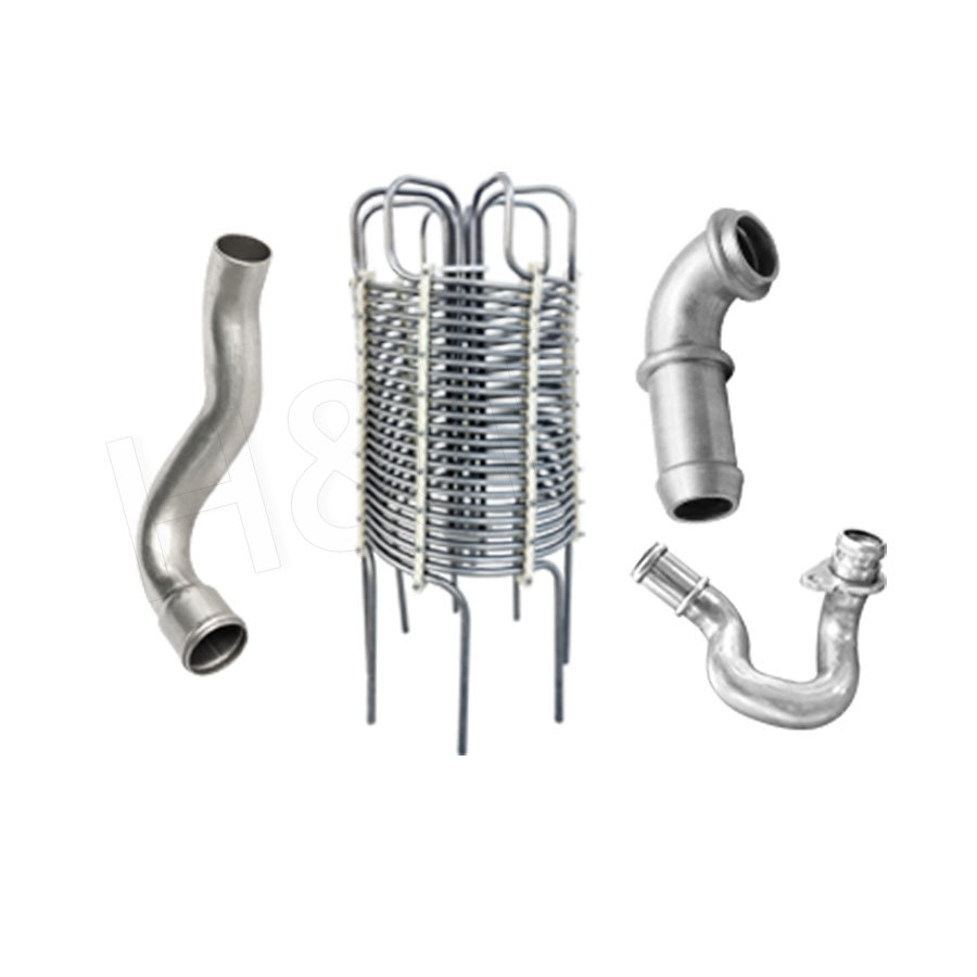
Precision tube fittings manufacture refers to the process of transforming raw metal tubes into high-accuracy components with specific, often complex geometric shapes, using advanced CNC tube bending machines, laser cutting, end forming, and welding technologies. The resulting parts—which range from simple right-angle bends to elaborate multi-plane configurations with dual U-shapes, corrugated profiles, spiral geometries, and multi-layer parallel tube bundles—serve as functional components in hydraulic and pneumatic systems, thermal management circuits, structural supports, and medical device assemblies.
What distinguishes precision tube fitting manufacture from general tube processing is the combination of geometric complexity, tight dimensional tolerances, and traceability that these parts require. In automotive applications, for example, a fuel rail tube must maintain a bend radius tolerance of ±0.3 mm and an end-to-end length tolerance of ±0.5 mm over a component measuring 600 mm—a level of accuracy that demands multi-axis CNC bending, in-process gauging, and tightly controlled material properties.
Core Manufacturing Processes
CNC Multi-Axis Tube Bending
CNC all-electric or servo-hydraulic tube bending machines with 5–7 controlled axes (bend axis, clamp, pressure die, carriage feed, tube rotation, and wiper die) produce complex multi-plane bend sequences from a single program. A fully CNC bending machine can execute a 10-bend automotive brake line configuration in under 40 seconds with bend angle repeatability of ±0.1°. Key bending variables that must be controlled include:
- Bending radius (R/D ratio): The ratio of bend centerline radius to tube OD determines wrinkling and ovalization risk. Tight-radius bends (R/D < 2) require mandrel support inside the tube to prevent collapse.
- Springback compensation: The CNC system automatically over-bends by a calculated amount (typically 1°–5° depending on material and bend radius) so that the tube springs back to the exact target angle after tool release.
- Tube rotation and feed indexing: Servo-controlled rotation (B-axis) and linear feed (Y-axis) position the tube precisely for each successive bend, enabling multi-plane 3D tube geometries.
Laser Tube Cutting
Fiber laser tube cutting machines (typically 1.5–6 kW laser power) cut tubes to length and create complex end preparations—saddle cuts, coped joints, slot patterns, and notches—with kerf widths below 0.3 mm and positional accuracy of ±0.1 mm. For structural tube fitting applications, laser-cut saddle joints eliminate the grinding and fitting work previously required for tube-to-tube welded joints, reducing joint preparation time by 70–80%.
End Forming Integration
Precision tube fittings frequently require end processing—flaring, beading, necking, or fitting insertion—to complete the assembly interface. CNC end forming machines integrated into the production flow process each tube end immediately after bending, maintaining component orientation and eliminating the dimensional accumulation error that occurs when parts are re-fixtured between separate processes.
Orbital and Robotic Welding
For tube assemblies requiring welded joints (e.g., manifolds, headers, T-branches), orbital TIG welding or robotic MIG/TIG welding produces consistent, high-quality joints with full fusion and controlled heat input. Orbital welding on tube ODs from Ø6 to Ø168 mm achieves 100% penetration welds at travel speeds of 50–200 mm/min, with weld bead geometry controlled to within ±15% of the nominal.
Precision Tube Fitting Geometries and Their Applications
| Geometry Type | Description | Typical Applications |
|---|---|---|
| Single-plane bend (L, U shapes) | 1–4 bends in one plane | Brake lines, coolant circuits |
| Multi-plane 3D bend | Bends in multiple planes, complex routing | Automotive underbody, aircraft hydraulics |
| Corrugated / serpentine | Alternating bends for flexibility or thermal cycling | Heat exchangers, vibration-absorbing lines |
| Spiral / helix | Continuous helical winding | Spring-back absorbers, heat coils |
| Double U / hairpin | Compact return-loop geometry | Refrigeration coils, EV battery cooling |
| Multi-layer parallel bundle | Multiple parallel tubes in a common bracket | Hydraulic manifolds, aerospace tube bundles |
Materials Used in Precision Tube Fittings
Material selection for precision tube fittings is determined by operating pressure, temperature range, corrosion environment, and weight constraints:
- Low-carbon steel (St37, SPCC): Most common for general hydraulic and automotive applications. Good formability; cold bending without annealing up to wall thicknesses of ~3 mm in standard grades.
- High-strength micro-alloy steel: Used in weight-critical automotive and off-highway applications. 30–40% lighter than equivalent carbon steel components due to higher yield strength allowing thinner walls at the same pressure rating.
- Stainless steel 304 / 316L: Preferred for food processing, pharmaceutical, and marine applications requiring corrosion resistance. More challenging to bend due to higher work-hardening rate; bend radii must be at least 2× tube OD to avoid cracking.
- Aluminum alloy 6061-T4 / 6063: Extensively used in EV battery cooling circuits and aerospace for its combination of low weight (density ~2.7 g/cm³ vs. 7.8 g/cm³ for steel) and good corrosion resistance. Requires annealing to T0 condition before tight-radius bending.
- Copper and copper alloys: Standard for HVAC and refrigeration tube fittings due to excellent thermal conductivity and brazeability. Very ductile; can be bent to R/D ratios as low as 1.0 without mandrel support in thin-wall configurations.
- Titanium Grade 9 (Ti-3Al-2.5V): Used in aerospace hydraulic lines where maximum weight reduction and corrosion resistance are required. Difficult to cold form; requires heated tooling or warm forming at 200–300°C for tight-radius bends.
Quality Standards and Dimensional Inspection
Precision tube fittings for automotive and aerospace are subject to rigorous dimensional inspection protocols, often mandated by OEM quality standards:
3D Coordinate Measurement (CMM / Tube Measurement Systems)
Dedicated tube measurement machines—essentially CNC CMMs optimized for long, bent components—use touch probes or optical sensors to measure the 3D centerline geometry of a finished tube and compare it to the CAD nominal. These systems report deviations at every bend and straight segment, identifying systematic bending errors. Measurement time for a 10-bend tube is typically 60–120 seconds, enabling 100% inspection in high-volume production.
Pressure Testing and Leak Detection
For hydraulic and fuel line assemblies, hydrostatic or pneumatic pressure testing verifies joint integrity and the absence of micro-cracks. Automotive brake tubes are typically proof-tested at 1.5–2× working pressure (up to 300 bar for brake systems), with helium leak detection for the most critical sealing requirements.
Surface and Coating Inspection
For corrosion-critical applications, zinc, zinc-nickel, or polymer coating thickness is verified using X-ray fluorescence (XRF) or magnetic induction gauging. Salt spray test compliance (typically 480–1,000 hours without red rust per OEM specifications) is validated during product qualification.
Design for Manufacturability in Precision Tube Fittings
Early collaboration between product designers and tube fabrication engineers can dramatically reduce manufacturing cost and lead time. Key design guidelines include:
- Minimum straight tangent length: A straight section of at least 1.5× tube OD must be maintained between adjacent bends and between a bend and a tube end, to allow clamping and die clearance during bending.
- Consistent bend radius throughout the component: Using a single bend radius across all bends in a part minimizes tooling requirements and reduces setup time. Mixed radii on the same part require additional tooling sets.
- Avoid compound angles near tube ends: Bends within 3× OD of a flared or beaded end are difficult to achieve without distorting the end form. Designing sufficient straight length before the end fitting facilitates both bending and end forming without interference.
- Specify ovalization tolerance: All bent tubes experience some cross-sectional ovalization. For fluid-flow applications, specifying a maximum ovalization (typically ≤5–8% of nominal OD) ensures flow coefficient requirements are met without mandating unnecessarily tight process controls.
Frequently Asked Questions About Precision Tube Fittings Manufacture
What is the tightest bend radius achievable for steel tubes?
For standard carbon steel tubes with a mandrel and wiper die, a bend centerline radius of 1.0–1.5× tube OD is typically achievable without cracking or excessive thinning, depending on the wall thickness ratio (D/t). Thicker walls (D/t < 15) tolerate tighter bends better than thin-wall tubes (D/t > 30).
How is a CNC bending program generated from a CAD model?
CAD tube geometry is exported as a centerline IGES or STEP file and imported into bending machine offline programming software, which calculates the YBC (Y-axis feed distance, B-axis rotation angle, C-axis bend angle) sequence for each bend, including springback compensation values specific to the material and tooling. The program can be simulated and collision-checked offline before the first physical tube is bent, saving setup scrap.
What causes wall thinning at the bend extrados, and how is it managed?
Wall thinning on the outside of the bend (extrados) is an inherent consequence of tensile stress during bending. For a bend radius of 2× OD, thinning is typically 10–15% of the original wall thickness. This is managed by starting with a tube whose wall thickness provides the required minimum thickness after thinning, using a pressure die to apply axial compression during bending (boost bending), and optimizing mandrel position to support the inner bend wall.
Can bent tube assemblies be straightened or reworked if they are out of tolerance?
Minor dimensional deviations (within ~1–2× the tolerance band) can sometimes be corrected by cold re-forming in a dedicated straightening fixture. However, rework is expensive and risks introducing residual stresses or surface damage; for safety-critical applications (automotive brake lines, aircraft hydraulics), re-forming is typically not permitted, and out-of-tolerance parts are scrapped. This reinforces the importance of process control and statistical monitoring to prevent non-conformances at the source.